Contents
Index
Adjust Job
This option uses all the cadastral dimensions together with control data to improve the coordinates generated
by the joining process. Equations are formed for each bearing, distance and line point and the initial
coordinates are varied to produce the optimum fit with the bearing, distance and line point data.
A weighting applies to all Bearings and Distances in the data.
For information on the weighting, see Adjustment Weighting
Bearings
Tolerances for bearings are specified in seconds of arc.
If the difference between the line computed from the initial coordinates and the measured line is greater than this value,
then a warning will be displayed as the adjustment is built
Default 6000 secs, stored in job file
Distances
Tolerances for distances are specified in metres.
If the difference between the line computed from the initial coordinates and the measured
line is greater than this value, then a warning will be displayed as the adjustment is built.
The adjustment will be stopped if any difference is greater than three times the tolerance.
This is a safeguard against including blunders.
Default 0.1m, stored in job file
Line Points
Line points are checked for their distance from the line that they are supposed to lie on and a check is
also made to see if the line point is close to either end of its line.
Default 0.1m, stored in job file
Close Points
The Close points check will flag any points closer than the specified distance which do not have a
dimension between them. This is a good way to find common points that have been missed in the joining process.
Default 0.2m, stored in job file
Enforce Line Points
Line points have been selected during the joining process.
If a line point is found within the tolerance specified, it will be forced back on to the line.
If it is outside the tolerance, a warning message will be given in the adjustment report.
The tick box is not stored in the job or the registry
Default 0.1m, stored in job file
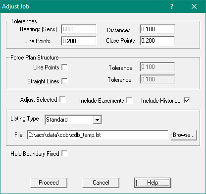
Enforce Straight Lines
The straight lines routine will enforce some of the original subdivision structure.
Where you have a series of adjacent lots in a plan where that front and/or the back lines each have the
same bearing, then the intention of the subdivider was for those lines to be collinear.
The straight lines routine will detect these types of plan structures,
and if the points are within the specified tolerances it will make these lines collinear.
The tick box is not stored in the job or the registry
Default 0.1m, stored in job file
Adjust Selected
This will only adjust the currently selected parcels.
The tick box is not stored in the job or the registry
Include Easements
In most cases, easements simply have to fit to the external boundary lines of a parcel.
If this box is not ticked, the easement dimensions will play no part in the adjustment process,
but will be used later to determine the easement corners after the parcel boundaries have been adjusted.
If the “include easement” box is ticked, all easement dimensions will be included in the
main adjustment process and given the same weighting as the parcel boundary lines.
The tick box is not stored in the job or the registry
Include Historical
Tick this box to include historical parcels in the adjustment
The tick box is not stored in the job or the registry
Listing Type
- No Listing
- Simple - This is a summarised version of the adjustment report
- Standard - This is the normal version of the adjustment report
- Extended - This gives full details in the adjustment report
The selection is not stored in the job or the registry
Listing File
The results will be written to the specified listing file.
or information on the layout of the file, see Adjustment Report
Hold Boundary Fixed
This treats edge or boundary points of the job as fixed and not to be adjusted.
The tick box is not stored in the job or the registry
Adjustment size
The maximum values that are currently set are:
Points:50,000 Parcels:5000 Unknowns:60,000 ATA Matrix300 million
The adjustment size is determined by a number of factors.
First, there is the number of node points and the number of parcels.
A node point is a point where more than two lines join. Each node point has two unknowns (X and Y)
and each parcel has one unknown (its orientation). So, the number of unknown values that have to be
resolved is twice the number of node points plus the number of parcels.
These generate the ATA Matrix and as only the upper triangular part is stored,
in the worst case the size of this is half the square of the number of unknowns plus half the number of unknowns.
So if there were 20,000 unknowns, a worst case would be 200,010,000 terms.
However, the program uses methods to limit the band width and this can reduce the size of the ATA matrix
depending on the structure of the data set.
From a practical point of view, it pays to limit the adjustment size to be less than 2000 parcels at a time.
The time for processing goes up roughly according to the square of the number of unknowns and therefore,
it can be counter productive to work with very large data sets.
Strata Lots
Only the lots on the ground floor of a strata subdivision are included when computing the least squares adjustment.
For the corners of the remaining lots, the procedure is as follows:
- Calculate plane coordinates for all the points in the plan in a local coordinate system.
- Mark the points in that collection which have been included in the adjustment.
- Use these points to compute helmert transformation parameters to go from the local coordinate system
to the adjusted coordinate system.
- Use these parameters to transform the points which were not included in the adjustment.